Approximating the Sierpinski Triangle on my CNC
Monday, July 15, 2024
One of my big hobbies outside of tech is chess. I like to play it, and I also help run our town's chess club. As part of that, we like to run rated tournaments to get our members some experience in a low-pressure tournament environment. These are my responsibility to organize and run, and our club's only certified tournament director.
We hosted our first tournament last winter. The whole thing went off well, except that I was supposed to have a prize medal for the winner. Our vendor fell through, and I had nothing except congratulations for the winner[1].
With our second tournament coming in May, I needed a solution. Or rather, I used the "solution" as an excuse to get a new toy. Instead of buying a medal, I'd buy a tool that I could use to make medals for the winners. And then they're also one-of-a-kind.
I made a simple model of a medal and convinced myself that this would work, I've somehow done it and figured it out. I could either make the medal on a 3D printer or I could cut it out of wood with an automated woodworking tool (called a CNC), and since I already have a well-equipped woodshop, I opted for the latter, to complement what I already have.
Before long, my very cheap CNC[2] arrived in the mail, and I had to get to work. But I didn't know what I was doing, so first I played to learn how to use it. And my first project was very fun, and accelerated my learning by containing many of the difficult cases I didn't run into for my real use case.
What's a CNC?
"CNC" means "computer numerical control", and it refers to tools which are automated and controlled by computers. This is in contrast to most tools, which are controlled manually with at best precise digital measurements.
Within the category of CNC, you have a lot of different tools. The most common are routers and mills, but the rest are interesting as well.
- CNC routers have spinny sharp bits on them that can cut slots, holes, fancy shapes, whatever! They move around on an x-y plane, but also have some z-axis depth control, so they work in 3 dimensions. Routers usually cut wood and soft materials.
- CNC mills also use spinny sharp bits, and are similar to routers. The distinction comes in their axes (mills tend to have smaller working areas, but much more depth capacity) and rigidity and torque (mills are much better at cutting harder things). Mills also tend to have more axes, such as 5, by adding rotation to be able to produce more complicated parts. You usually cut metal and hard materials on a mill.
- 3D printers are CNC!
- Laser cutters are CNC!
- You can have a CNC lathe!
The category is gigantic. In my case, I got a CNC router, but I often say I'm milling something on it. Now let's see how we do that.
How do we CNC something?
See, while I had made a model and bought the CNC, I hadn't accounted for any of the rest of the process of actually milling something. In my head, the process for making something on the CNC was roughly:
- Design the part in CAD.
- Run it on the CNC and get finished part!
This illusion was shattered when one of my friends who does a lot of 3D printing asked me what I was using for my CAM software. "CAM software? Uhhh..."
It turns out, after you make a part in CAD, you then have to convert that into tool paths for the machine. These are the instructions for how it moves around, how fast it spins the motor, and, well, everything it does. The software that does that is called CAM (computer-aided machining), and it turns out it's not trivial. And if you design your part without toolpaths in mind, you'll likely make a part that you can't actually mill!
So the real process for making something on my CNC is more like:
- Design the part in CAD.
- Put it into CAM and make toolpaths, then go to 1 to fix design mistakes. Repeat a lot.
- Upload it to my CNC, run it, break a bit, and go to 2 to fix toolpath mistakes.
Fixing bugs in a physical manufacturing process can be a lot slower and more expensive than in software.
Let's look at what I wanted to make, then see how to do it. Since I'm a Linux user, this process required using some less common tools; the usual ones are Windows/Mac only.
What's the Sierpinski triangle?
A fractal is basically a shape that's self-repeating. The most famous fractal is probably the famed Mandelbrot set. This one would be fun to make, but the rapid approach toward infinitely small curves makes it hard to mill.
Instead, I picked the Sierpinski triangle, which is another fractal. It starts with an equilateral triangle. Then inside of it, you draw another equilateral triangle, upside down. This partitions it into 3 "up-facing" triangles and 1 "down-facing" triangle. Then you just repeat this process (smaller!) inside each of the up-facing triangles.

Here we can see four iterations of it. The real fractal goes on infinitely, getting infinitesimally small. This forms a fascinating image. And more important for my purposes, it's something you can sort of mill! Obviously you can't go infinitely small in a physical process, but it's a lot easier to approximate this than it is to approximate a Mandelbrot set on my CNC.
So now we have to turn it into something on the computer, working our way closer to instructions the CNC uses.
Modeling it with OpenSCAD
The first step for me was modeling it with a CAD program. This is a natural fit for OpenSCAD, which lets you generate models through code[3]. I'd dabbled before to make a proof-of-concept model of a prize medal, but doing this required me to go deeper into OpenSCAD and start using functions and modules.
The strategy I took for modeling this was to first focus on generating a model of the triangle, with each iteration stacked atop the previous one, and then separately figure out how to remove that from the wood block we're going to be working with. This turned out to be very helpful for debugging, since I could separate out the layers—if this were subtracted out of our stock, those would be stuck invisibly inside a block! After we have the triangle model, we'll make a rectangular prism (our block of wood) and subtract our triangle out of it.
My first step was laying out some parameters for the model as constants.
This way, if we need to change anything, we can update these.
INCH is included as a constant, since OpenSCAD is unitless, but I'm working with it assuming it is millimeters (which my CNC expects) while my woodworking equipment is in Imperial units (tablesaw and thickness planer in particular).
You'll notice that the layers are very thin, less than 1mm!
That's because, again, my CNC is cheap and slow, and any more than that was going to take far too long to produce.
But let's call it an ✨ aesthetic choice ✨.
INCH=25.4;
buffer=0.5*INCH;
width=4*INCH + buffer;
thickness=0.25*INCH;
layer_height=0.75;
For this model, I took a very iterative approach, drawing from all my software engineering experience. (I don't know what the equivalent of a unit test would be in this world, though. If you do, please let me know!) To start out, I made a model of the Sierpinski triangle in OpenSCAD. I did one layer first, to get an equilateral triangle rendering. Here are some of the functions I ended up with[4].
function sq(a) = a*a;

function midpoint(a, b) = [(b[0]+a[0])/2, (b[1]+a[1])/2];

function triangle_top(a, b) =
    let (length = sqrt(sq(a[0]-b[0]) + sq(a[1]-b[1])),
        height = length * sqrt(3) / 2,
        mp = midpoint(a,b),
        xd = (b[1]-a[1]) / length * height,
        yd = (b[0]-a[0]) / length * height)
     [mp[0] - xd, mp[1] + yd];

module eq_triangle(a, b) {
    c = triangle_top(a, b);
    points = [a, b, c];
    offset(1.5, $fn=20)offset(delta=-3)offset(1.5)polygon(points);
}
Then I did the iterative step, to work out the math of it. One of my early attempts wound up with this beauty:

I do think that I made art here, but it's really not what I was going for—and it's not going to be something I can mill! So I fixed my math, and with some struggles I got a working model. Here's the module for that, along with the render.
module sierpinski(layers, width) {
    origin = [0,0];
    a = origin;
    b = [origin[0]+width, origin[1]];
    mp = midpoint(a, b);

    // to subtract it out of the block instead, use 1*layer_height
    translate([0,0,1*layer_height]) {
        linear_extrude(layer_height+0.1) {
            eq_triangle(a, b);
        }

    if (layers > 0) {
            translate([0,0,0])
            sierpinski(layers-1, width/2);

            translate([mp[0],mp[1],0])
            sierpinski(layers-1, width/2);

            tt = triangle_top(a, mp);
            translate([tt[0],tt[1],0])
            sierpinski(layers-1, width/2);
        }
    }
}

You'll notice that this looks sorta like some of those kids' building blocks from a notoriously litigious toy company. Why's that? Because if you have two straight edges contacting each other, OpenSCAD will happily display it but will then complain about a 2-manifold something-or-another when you try to render it for real[5]. One of my friends explained that this is because the model is assumed to have those properties for optimization purposes (renders can already be slow) so if they're violated, such as two straight edges contacting each other that have nothing else attached to them, it can't compute the model! We resolve this by adding a fillet on the inner corners so they're rounded, and we get this look!
This is ultimately to our benefit, though, because we can't produce sharp inner corners on the CNC. We're using a round bit, spinning in circles. So this better models what will actually happen on the CNC, and we'll get fewer surprises in the later steps.
Now we have a Sierpinski triangle going upways, but we ultimately want to cut it out of our stock. To do that I adjusted a constant. I could probably actually flip it in the model, but I was tired and picked the first thing that worked. And then we subtract the flipped model out of our stock!
difference() {
    linear_extrude(thickness) {
        square([width,width*sqrt(3)/2]);
    };
    translate([buffer/2,buffer/2,thickness]) {
        sierpinski(5, width - buffer);
    };
}

Whew, now we have the model! That was the hard part, right? ...Right? Ahhh hahaha, sweet summer child that I was.
Turning it into commands for the CNC
This is the part where we break out the CAM software. CAM (computer-aided machining) software turns your model into commands that your machine can run. This is often G-code. You can think of G-code as sort of like assembly code that a CNC runs.
Here's a snippet from one of my models:
G21
G90
M3 S1000
G0 X1.4560 Y0.6702 F6000
G0 Z1.0 F300
G1 Z-0.6250 F250
G1 X2.3053 Y0.2921 F500
Each of these commands either sets a mode on the machine (G21 sets the unit to be millimeters) or performs a command (M3 starts the spindle, G0 and G1 are forms of movement). This would be incredibly tedious to write out by hand, but it's theoretically doable[6].
To get the model into this form, we pop it into our CAM software and do some work. The CAM software I use is Kiri:moto. This software is a whole other thing you have to learn.
The crux of it is this: You tell it which operations you want the machine to do, and then it tries to figure out how to do it. Along the way, there are a ton of parameters to tune. Of course you have to tell it the tools you have (in my case, a 1mm endmill bit) and it has to know some information about your CNC. And then for each operation, you need to tell it things like how fast to turn the spindle, how much to move over or down on each pass, if you want to leave excess material (very handy to do rough passes first, then come back and clean it up).
Here's what it looks like from my most recent run of this model.

When I first opened this software, I was overwhelmed. What are all these boxes? You don't have to understand each of them, but understanding them will help you avoid broken bits and repeated trial runs on your CNC.
What's really handy are the preview and animation tabs, which let you see the paths it's going to generate and watch it pretend to mill out your part. Really neat, and a good way to validate a design!
After something looks good in your CAM software (which took me as long as modeling the part the first time, but is a lot faster now), then you download the G-code and go to the workshop to run it.
Making it real
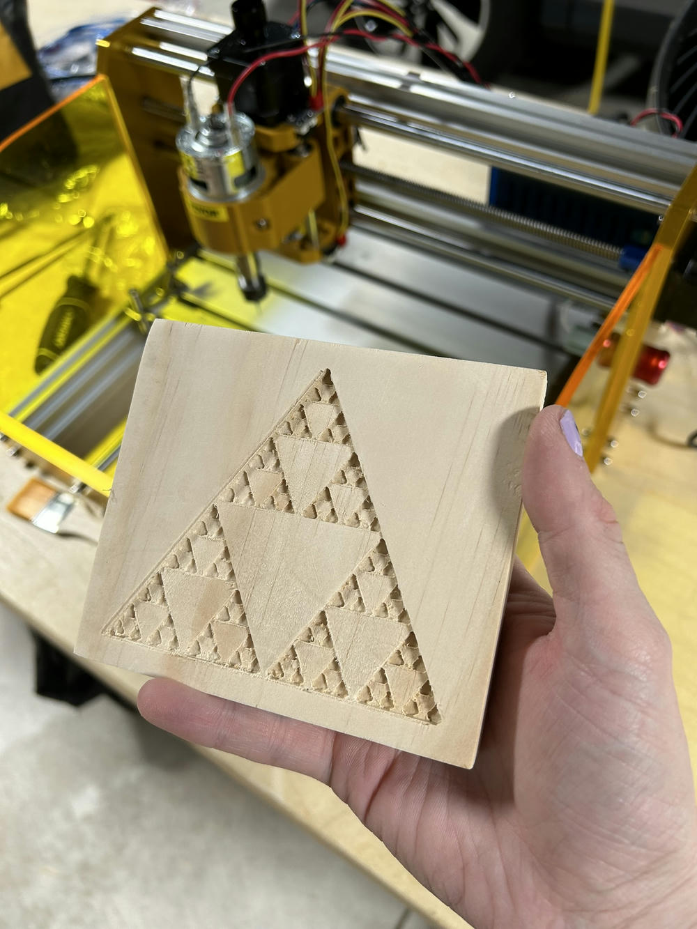
With the G-code in hand, I ran to the workshop and made the part. And it worked! I was happy with it, but also... It had blemishes and it had artifacts from the machining, where my toolpaths were clearly bad. It was rough, and it showed my inexperience. So I did it again, and the second one I made is where I learned a lot of ways to improve (and some more silly mistakes to make).
Here's the first one, fresh off the machine.
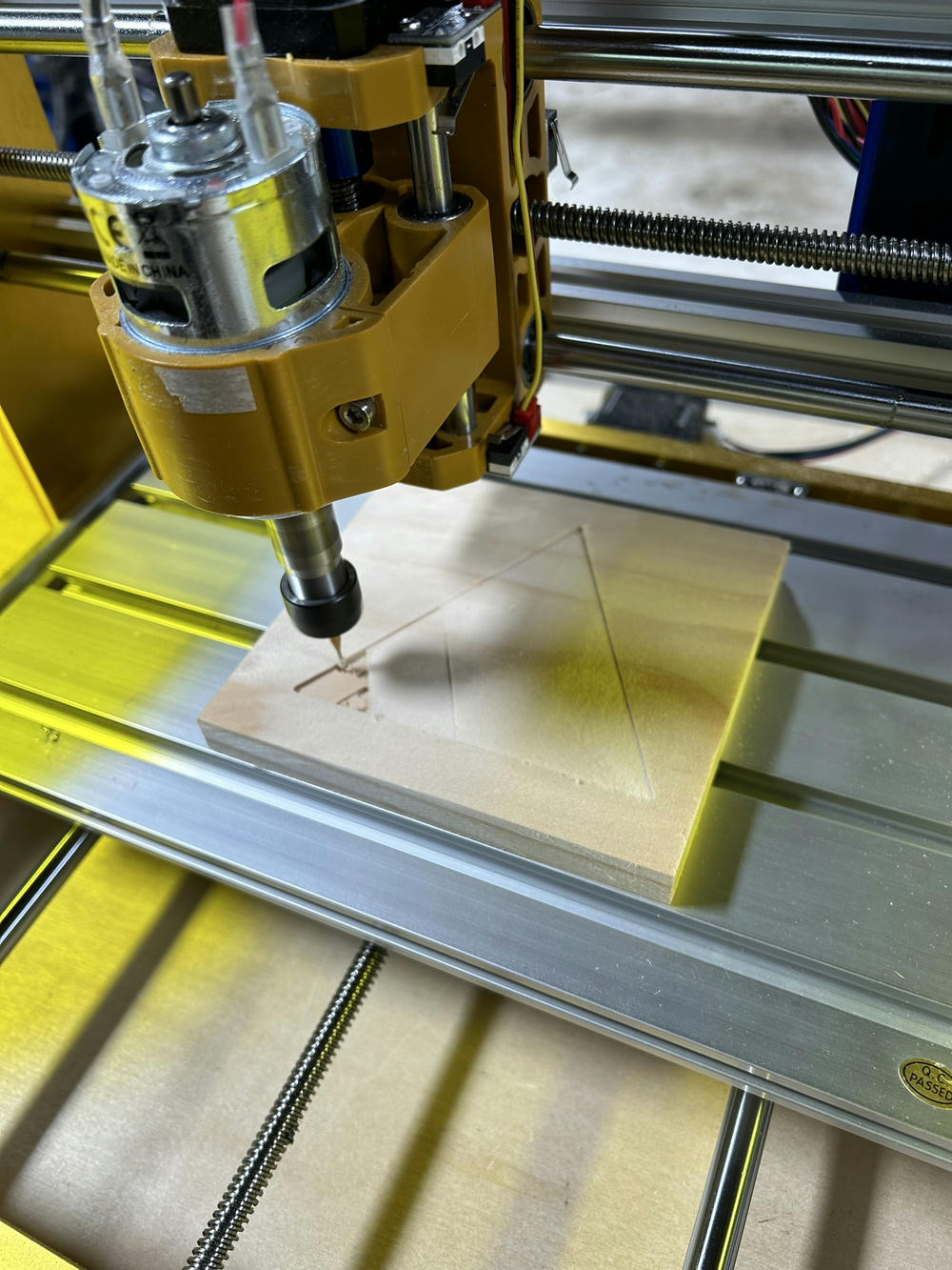
Then the second one in progress.
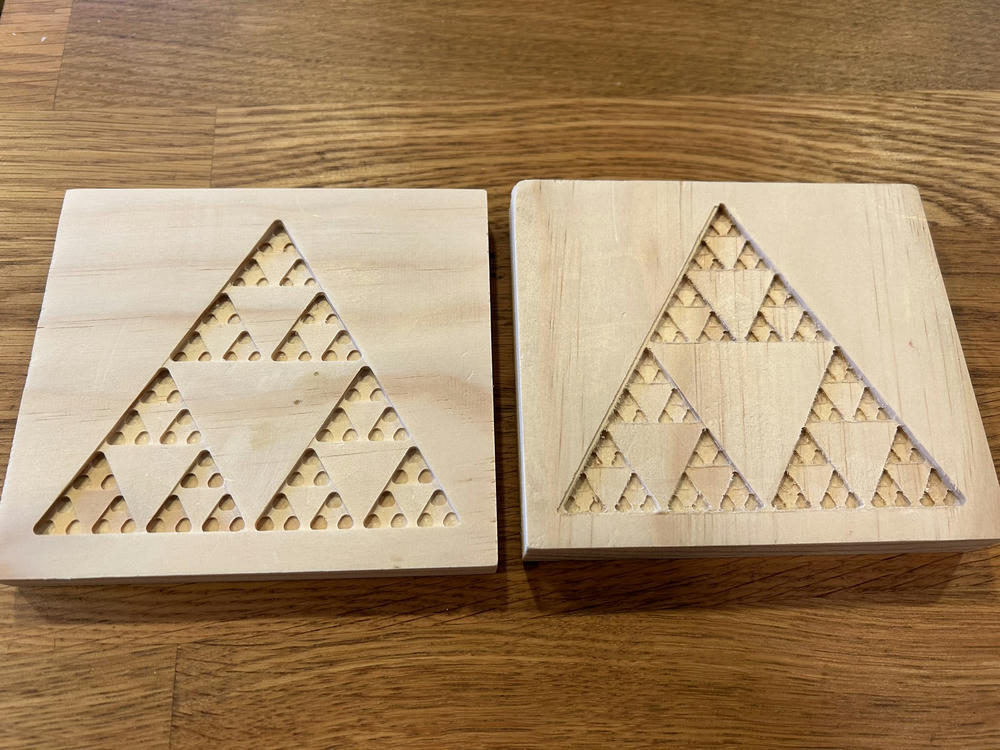
And finally, the second one side-by-side with the first one. The second is on the left (I'm a monster, sorry), and if you zoom in on the vertices of the triangles of each, you can really see the artifacts on the first one. It's so sloppy! The second one is so clean!
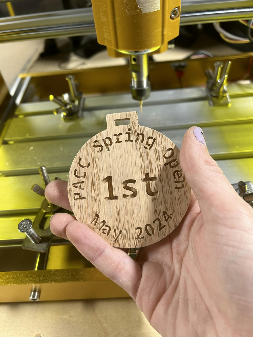
As a bonus, here's the oak medal I made for a chess tournament, also fresh off the CNC. I finished in time, with a day or two to spare, and the tournament went off without a hitch!
Broken bits and deep soulful joy
This project taught me a lot of lessons very quickly. I broke a few bits making part and left scars on my machine. Each time it was for something silly, and each one was a lesson. A lesson in setting up parts on the machine. In designing good toolpaths to improve schedules and end results. In how to remove parts from the machine without breaking them or your bits. And in how to design things that can be physically produced.
The lessons are hard-won and each time it usually comes with some physical marker of your failure. Maybe it's a broken bit that you needed to produce your part, so you're blocked until new ones arrive. Or maybe it's a ruined part and a lost day's work. Or maybe it's physical scars on your machine, forever commemorating that silly mistake.
These hard-won lessons can wear you down.
The iterations were long, and each time I was sort of wondering, why is it that I'm doing this? Fixing bugs in software is usually a lot faster and doesn't result in wasted material. But when it worked? Then I remembered exactly why I'm doing this.
Because making physical things is joyous and makes my soul sing. There is a joy that I get from holding a small little piece that I made that is so often missing in my work as a software engineer.
It doesn't matter what it is, making physical things is a joyous and vexing process. Baking a cake, making a fractal, framing a photo. Each of these connects me to reality and grounds me in our physical world in a way that's often missing from software alone.
Getting to hold a thing you made, and show it to a friend? It makes all the broken bits worth it.
Thank you to Dan Reich for the helpful feedback on a draft of this post!
-
If for some reason he's reading this (or you know him; he's not from our club), email me! I'd love to hook you up with a retroactive medal. ↩
-
I'm talking $250 cheap. This thing isn't going to do well on metal, and it won't win any speed awards, but it can do small jobs in wood. ↩
-
I did also try modeling some other things with FreeCAD, not least because you can do CAM inside it as well. I had it crash on me repeatedly, and it doesn't fit my brain as well as OpenSCAD (since I'm first and foremost a programmer). Maybe I'll try out another one someday, but so far OpenSCAD is treating me well! ↩
-
The
offsetbits are to fillet the corners, which comes back around later. This code is presented in the logical order, but not chronological order that I developed it in. I don't think anyone needs to see the chaos that is my development process. ↩ -
Now I can get the model to render without this issue and without fillets, I think because all the layers touch and it's in the stock. But at any rate, this better shows what will actually happen on the CNC. ↩
-
For another project that's going on in the background, but delayed due to health issues, I'm planning to generate G-code directly from another program. Still not doing it by hand, but I'll have to do a lot of inspection and reading of the G-code. ↩
If you're looking for help on a software project, please consider working with me!
Please share this post, and subscribe to the newsletter or RSS feed. You can email my personal email with any comments or questions.
Want to become a better programmer?
Join the Recurse Center!
Want to hire great programmers?
Hire via Recurse Center!